Had some time today and so I decided to go for the hazard light switch mod. Found a nice place on the left mirror stem to mount the switch. Wiring was pretty straightforward.
Opened up the head unit by removing 4 large bolts on the side of the head unit – 2 on the left and 2 on the right.
Then locate the signal lights connectors – the grey and green 2-pin connectors (see pictures). All you need to do it to tap any 2 of the switch wires into the GREEN and GREY wires. Note – Do NOT tap into the black/yellow wire – that’s GROUND and you’ll end up with a short circuit.
The third switch wire is meant to be connected to the flasher relay output. I tried to wire it to the bike’s existing flasher relay’s ORANGE wire, but it didn’t seem to work. Perhaps I may need a separate flasher for this.
But nevertheless, even without the 3rd wire connected, when the hazard switch is depressed AND any of the signal light is activated (either left or right, it doesn’t matter), the bike now blinks all 4 signal lights. So effectively, it’s a 2-step hazard light process.
My initial intent was to have the hazard switch blinking all signal lights WITHOUT having to use the signal switch. Was tired at the end of this exercise. Didn’t want to troubleshoot anymore. Perhaps I’ll add on a flasher relay to make this happen at another DIY session.
UPDATE: The wiring at the flasher relay output was not connected properly. Reseated the wire and it now works! Hazard light WITHOUT needing to turn the signal switch!
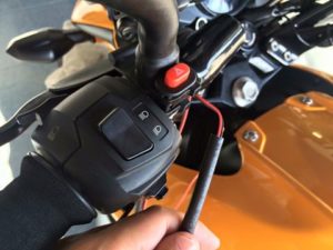
Location of the hazard light switch.
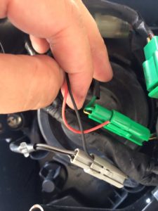
The left and right signal lights connector within the headlight unit. GREEN and GREY for 12v signal, and BLACK/YELLOW is ground.
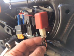
The red module here is the flasher relay. Located on the right hand side of the bike. The BROWN wire is 12V and ORANGE wire is the output.
BTW, I tapped the BROWN wire for 12V “ignition ON” in a separate project. This wire provides 12V only when the bike switch is turned ON.
Hi Derrick,
AMAZING site you have got here. Very good to know about all the mods that you have done on the bike.
I too own a pulsar 200ns 2012 model and now Coming to the question. Can u guide me on how to install an USB mobile charger on the bike and powering it ON only when the key is switched to ignition?
It would be a lot of help if you even posted some pics of the wiring. Thanks a lot. RIDE SAFE.
There are 2 ways to do it – the lazy way, or the proper way.
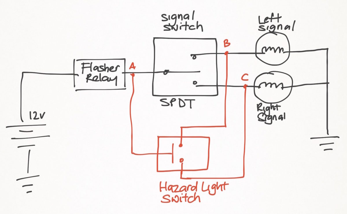
First, the lazy way (which I believe many mechanics will probably use, including mine when I first installed the USB power). Tap the power from ANY of the ignition on source. You will need to locate on near where you intend to place the USB adapter. One recommendation is the signal relay pictured above – that’s the BROWN wire and point “A” in the above schematic.
Then the proper way. You should really add a separate relay to isolate all your various add-on circuits from the bike’s original circuit. This relay acts as a “switch” and power comes directly from the battery. The current draw to actuate the relay is typically in the mA range, and you should be able to safely tap this signal from any “ignition on” source – again, an example is the signal / flasher relay above. I’ve sketched out the plans in my other post here:
http://sgbikerboy.com/2016/03/13/wiring-up-for-power-on-the-pulsar-200ns/
Thank you for the response. Should I connect the negative to the battery negative terminal? Can u post a pic of the negative connection.?
And one more thing. The brown wire running in the circuit, I can tap it without splicing the wires? Please post a pic for that also (how did u tap the wire physically).
You can either connect the negative end to the negative terminal of the battery (long wire run), or you can connect it to any metal part of your bike’s frame. In case you didn’t know, the whole of the bike’s metal frame is electrically connected to the battery’s negative terminal – this is called “grounding”.
You could either splice the wire (not recommended), or like me, you could disconnect the molex and then (very carefully) insert the stripped wire into female part of the molex where the BROWN wire is and then reconnect the molex back. This method is less secure and may be prone to coming out due to vibrations if not seated properly.
Wow… Thanks a lot… I have never had such a good response from any other site.
Thanks a lot for your patience.
I learned a lot from you.
I will get on this project right away and let you know how it goes. Thanks a lot for the help. I will keep in touch. ☺️
Good luck!
dear sir
I own a 2014 ns 200 assembled in Iran and now I want to add a LED daylight to it ( working with kill switch on right hand control switch.
Please guide me how to do this .
Thank you
Have you checked out my write up on “Wiring Up for Power on the Pulsar 200NS”?
http://sgbikerboy.com/2016/03/13/wiring-up-for-power-on-the-pulsar-200ns/
Nice tutorial. By the way, I see on youtube, there are people who use diodes (IN4001 or IN4007) before going to signal lights. What do you think? What are the advantages and disadvantages of using diodes compared to not using diodes?
The diodes are used a “electrical one-way valves”. You’d need to connect them correctly to work. Personally, I prefer a simpler solution.
what if indicators and hazard lights are turned on at same time?
That’s why is best to use the diodes. 😉