Had previously installed my bikecam and USB power port at a bike shop. What the mechanic did was to hard wire the bikecam and USB outlet to a “Ignition ON” wire on the bike. No fuse. When I asked him what if one of these cheapo made-in-China stuff short circuits? He told me that the main fuse will blow lor.
I never liked the idea of blowing the vehicle’s fuse with these “add-on” stuff. Because, the quality of these stuff are sometimes questionable, and blowing the fuse will leave you stranded.
I’d much rather have a separate circuit with its own fuse to support these aftermarket electronic add ons. So, I headed to the drawing board and came up with this…
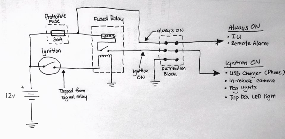
Edit: Subsequently repalced the 30A fuse with a 10A, and the 20A fuse with a 5A one instead.
Hi Derrick,
I am going to install a v-sys cam on my bike but I can’t seem to figure out how to ground wires. I am just using a relay and will do without a distribution block since I do not intend to install any other accessories. From my research it seems that some people attach the ground wire from the relay directly to the battery negative terminal whereas some attach it to the electrical ground. And from what I understand, I also need to ground the cam and it is again, done by attaching the wire to the battery negative terminal or to electrical grounding. Pretty confused here so hopefully you can help me shed some light on this. Please save me!
Almost the entire metal bike frame IS connected to the battery’s negative terminal. So for low power devices like your cam, it doesn’t matter if you connected it to the batt terminal or a metal point on your bike frame. To confirm the point that you want to attach is indeed grounded, use the ohmmeter on your multimeter. It should read zero ohms between the batt negative terminal and the grounding point.
Alright I’ll test it out. Thanks!
Try it out! Otherwise most bike shops will charge you somewhere between $10 and $30. You an choose to pay for it once and then observe how they do it. That was how I started myself. 🙂
Hey thanx for this very helpful post buddy.
I am thinking of installing a set of fog lamps myself, but i don’t know where to tap the signal relay from. Can you help me with the location of the ignition wire?
Also, how’s the 10A and 5A fuse setup working out?
Hey Vivek. I’m assuming you’re riding the Pulsar 200NS? The signal relay is that red boxy looking thing on the RH side of the bike. You’ll need to remove the side panel to access it. The “ignition on” wire is the BROWN wire connected to the signal relay.
I’ve some pics on my other post here:
http://sgbikerboy.com/2016/04/02/weekend-200ns-hazard-light-project/
Both the fuses seem to be doing their job. But then, I never really had to use them and neither of them have blown-up on me yet.
Yes, the same bike.
http://sgbikerboy.com/wp-content/uploads/2016/05/12919861_10153879322985783_3114824150143288816_n.jpg
The brown wire in this picture?
Also, my fog lights are 36w. So they would draw a maximum of 3 amps (36w/12v). So the 5a fused relay would be enough. Correct me if i am wrong.
Yes – the brown wire in the picture.
But if you’re trying to power fog lamps, I wouldn’t draw power directly from the signal relay if I were you. Reason being, that I’m pretty sure that it was designed for a relatively low power application and I don’t know what the fuse rating is upstream.
What I would do, however, is to use this BROWN ignition on as a signal to switch a relay. A relay uses relatively low power (in the mA range). Then get the relay to switch a separate circuit that draws power directly from the battery – just like the example in the blog post.
Yes, i am planning to install the lights using the relay setup as you have done.
Thank you for the input, I’ll try it out and revert back with the results.
Another hiccup, i am unable to source the 5 amp relay here in India. Any problems with using a 30 amp one?
I’m pretty sure you will be able to find it from a good hardware store. A 30 amp fuse is almost as good as no fuse at all as I’m pretty sure the wiring of the fog lights are so thin, that they’ll typically burn up before the fuse blows leading to a fire hazard.
No, seriously, I wouldn’t use a 30A fuse here.
Hello Sgbikerboy,
This is a little off topic, but here’s what i want to do to my ns 200. The pilot lamps and other lights which only come on after starting the bike to come on as soon as i turn the key on. i located the relay for this, which has 4 wires. i wanted to know where the black/yellow and blue/yellow wires come from? shorting the other two wires brings all the lights on with bike not started.
I could be quite wrong – but I believe the black/yellow wires are ground, and the blue/yellow is ignition on.
But why would you want to mess with these?
Hi Sgbikerboy,
I found a service manual, the second wire was blue/white not blue/yellow. The blue/White wire comes from the magneto, and triggers the relay as the engine starts running, ultimately switching the drl’s and low beam etc
Thanks man, loving your blog.
Hello Ketan ,
The service manual you found is it for the 2013 model ? Otherwise, may I know where to get it ?
Thank you and regards
I wanted to alter that particular functionality (headlight control unit) as stated in the service manual, so that i could switch on my pilot lamps and low beam/high beam on even when the engine is not running, or say if my bikes engine cuts off due to any issue while i am riding my bike’s headlight would still stay on, by default the headlight/pilot lamps/number plate light/speedo console lights/handle bar switch gear lights switches off if the engine cuts off and work only with engine on. if i breakdown i want the lights to work. (pass light works by default even with engine off) this is the unit http://tinypic.com/r/2hd3ynq/9 i removed the module short the wires going to the white connector, and tape the blue connector alone, wires to which comes directly from magneto and act as trigger/sense engine on as magneto produces current after the engine is started and triggers the relay. combined load of lights mentioned above without the headlight on is 450 miliamps to that not a problem, just dont forget to switch off the headlight when not in use and with engine off.
Hi,
First of all, your blog is great reading for me a newbie rider. I am considering installing some electrical accessories (voltmeter, usb charger etc) on my bike. May I know where do you get your stuff from, such as your fog lights, hazard light button, and also where to buy the electrical components such as the distribution boards and relays? If possible, can you show a photo of the relays and distribution boards?
Thanks!
I get them from various online stores – typically dx, gearbest, alibaba, taobao, aliexpress, banggood, geekbuying, just to name a few.
Can you show me how your distribution box set-up looks like? Thanks!
Hey Zed. This is not my pic (found this on the internet), but my “distribution box” or rather “distribution junction” is a very simple (primitive) wiring connector something like this…
Would have loved to use a proper fuse box, but the underseat real estate on the Pulsar is really, really limited.
your blog is great man i really enjoyed reading and learning from you. just wanna ask how did you tapped from the signal relay? do you have any pictures of it? thanks for your help. btw, do u happen to know if the wiring for ns200 is the same for ns150 coz i have the ns150 version 🙂
Pics here:
http://sgbikerboy.com/2016/04/02/weekend-200ns-hazard-light-project/
Sorry, I’m not familiar with the NS150.
Hi sgbikerboy
Can you help me here?
I want to install a mini voltmeter to my NS200 in such a way that it switches on along with the ignition and shows the battery voltage. However, right when i crank the engine it starts showing the charging voltage flowing towards the battery. The voltmeter i am talking about can take only DC voltage upto 30V so i suppose it can be converted into DC by adding a rectifier.
Really need to guidance on the wiring.
Hi Siddhant. Personally, I tap the “ignition on” from the input to the (signal lights) flasher module. It’s the BROWN wire. I’ve some pics here:
http://sgbikerboy.com/2016/04/02/weekend-200ns-hazard-light-project/
And BYW, you don’t need an additional rectifier. That is already a rectified 12V DC – not AC.
Okay. But would it show the charging voltage i.e ~14.2v ? It would be of little use if it always displays the battery voltage.
Theoraticlly, there should be no difference between measuring the voltage there and directly across the battery. Practically, due to slight internal resistance of the wires, there may be a small difference. To assure yourself, measure the voltage at both locations and decide for yourself.
Eureka. It works flawlessly now. Thank you so much for your time. I hope, in future i can discuss with you some other customization also on NS. 🙂
Glad it’s working for you!
Hi Derrick,
My name Rendy from Indonesia. I am curious, how the physical form of distribution block you make? Can you post the real photo? I am also curious, how do you determine the ampere quantity of 30A and 20A fuses? Then, why should be replaced with 20A and 5A? thank you sir. God bless
Hi Rendy. It’s not much different from what I’ve recently done to my recently purchased bike – the Honda CB400X. You can find some pics here:
http://sgbikerboy.com/2017/11/15/cb400x-12v-power-distribution/
The higher the ampere rating fuses will allow more current through, but will provide less protection. I did a rough calculation as to the max current the setup would draw, then add a 20% or so overhead, and then selected the fuse rating from there. With those thin wires used, do NOT use a 20A or a 30A fuse. In an electrical short circuit, the wires would likely burn up before the fuse blows! This *WILL* lead to an electrical fire!
Hi Derrick, thanks for the explanation. Very helpful. I have just tried to install a relay with the scheme: number 30 before the ignition, 87 after the ignition key, 85 ground, and 86 to the ignition on cable (after additional safety device). but that happens hot relay. I do not know whether the heat is natural or not. but I think it’s hot (not warm). I use 12v 30a bosch relay. I use one fuse 20a. Is the fuse value appropriate? or because the positive current flowing from the ignition key is so large that the relay gets hot? I plug the relay with this scheme because I installed an additional security device. Then I installed the volt meter accessories as well. For relay 86, I use a positive cable after a safety device with the intention that the volt meter lights up after the safety device is on. But the voltage numbers in the volt meter drop considerably. In battery voltage 14,6v, but in volt meter only 13,2v. I suspect there is resistance from the cable. Safety devices are placed under the back seat. Cable to safety device 1 meter, then from safety device back to ignition 1 meter (so total 2 meter). Any suggestion? Thank you sir
sorry there is a correction, I mean relay number 30 after the ignition key but before the safety device. number 87 after the security device and reconnected to the cable after ignition. so this safety tool works to break the current after the ignition. so when the ignition key is on, the pin must be inserted first in the safety device to make ignition on. thank you sir
That all sounds so confusing… Do you have a schematic sketched out?
What is your email address? Because I can not post images here
You’ve got PM.
Ok Derrick. I have sent the schematic to your email. Thank you
Hello.
I am not very good with electrical diagrams. But correct me if I’m wrong. I should wire it as follows:
10A fused wiring from battery to a new relay number 30.
Tapped from Flasher relay BROWN wire to new relay number 86.
Number 85 of new relay to battery -ve terminal.
Number 87 of new relay to the USB charger +ve.
USB charger -ve to battery -ve.
This way the USB charger will work only when ignition is on. In addition, I dont understand how to wire the 10A fuse to the 5A fused relay.
Looks about right.
Thanks alot! Where did you get you USB charger?
Hi, I am customizing my pulsar ns200, do you happen to have the electrical diagram ??
thank you